Weekly Progress
Week 16: 5/1/23 - 5/7/23
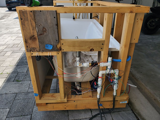
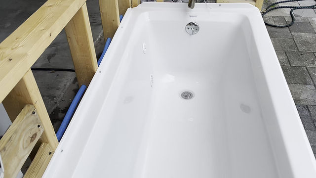
Kenneth - Transported tub to final testing location. The tub framing and plumbing is mostly complete. The drain system will still need work. The solenoids for hot and cold water have been installed as well as the heating unit and pump. Some things that I noticed while building:
1. In future models where the shape of the tub can be controlled, flat surfaces should be used where the water intake and output meet the tub walls. This will help the contact surface remain leak free.
2. The pump we are using requires at least a 3" drop from pump to intake and at least a 3" rise from pump to output. This requires this tub to be completely full to demonstrate the heating element.
These issues seem to be limiting the build in some sense but could be avoided using a custom tub that just happens to be out of the budget for our prototype. Some pictures of the build progress are shown.
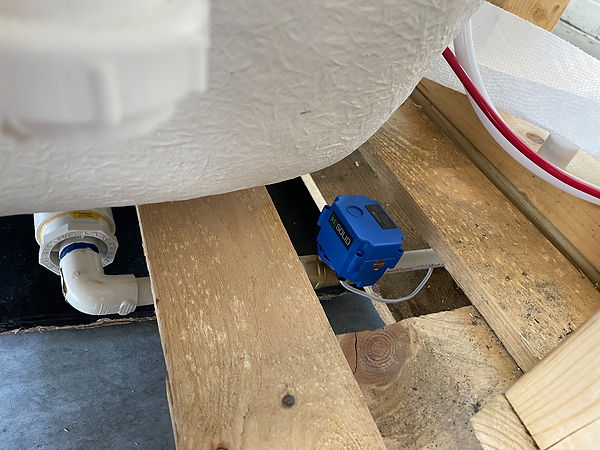
The solenoids are in place for the hot and cold water. They have been tested for water tightness. Quick release hose valves were added to the bottom for quick hook up during testing.
The flowmeter will be installed on this pipe. Whether it is installed vertically or horizontally will depend on the space in the area.
The water heater and pump installed. A block was used to support the pump to the proper height within the framing.
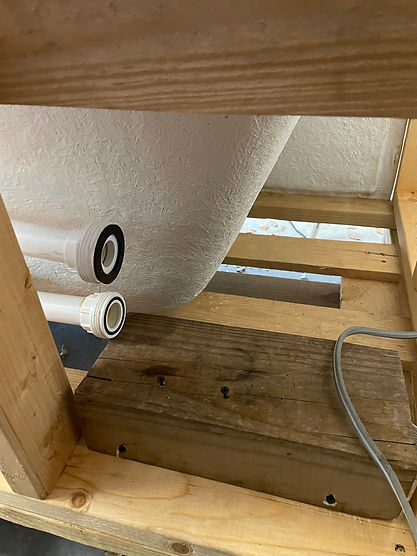
The intake valve and output for the water heater/pump. drilled through and sealed at the proper specifications.
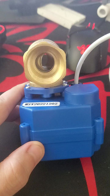
Ruben - Discovered potential point of failure with drain solenoid overheating during the bath due to the time it is active. Initial plan to buy and torture test a second solenoid to determine how long before it failed was unsuccessful due to the solenoid out of stock. A ball valve was found to be a better solution since it only uses power when transitioning from one state to the other.
Group - Began waterproof testing. One small leak due to the hose fitting not being screwed on fully was found, but the plumbing tested watertight.


Week 17: 5/8/23 - 5/14/23
Kenneth - I began diving into the water heating pump now that it is plumbed into the framing. The pump is controlled by a SPDT air switch. This was not specified in the description before purchasing. Neither Ruben or myself have any experience with air switches but the wring diagram seems to show we can bypass the switch all together and hardwire the unit directly to the PCB with a relay. This is an ideal situation because it will allow us to omit the Wi-Fi plug from the equation. The pump is fitted with quick release valves so it can be removed and worked on. Ruben is taking it home to test it with the other hardware items.
A rough diagram of the air button in reference to the pump.
A couple images of the quick release on the pump after it was removed.
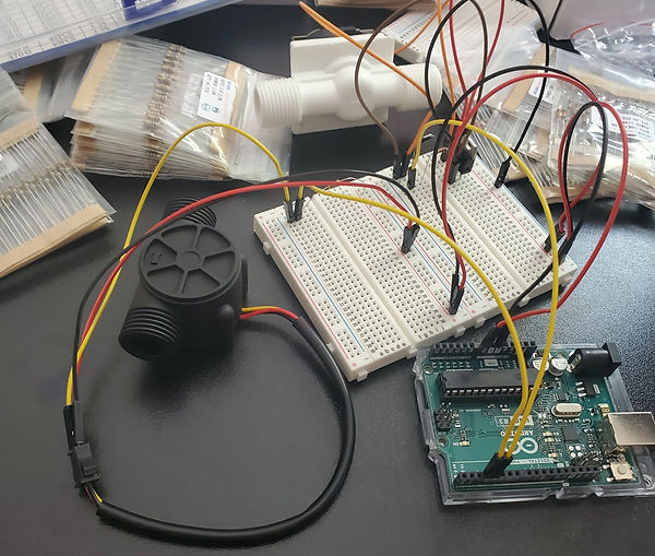
Ruben - I have began build the circuits and programming with the arduino to control them. I am initially writing basic programs to test the circuits and components before integrating them with one program that controls them all. Each test circuit will be rewired with neatly cut to length wires to prevent dethatching from the breadboard. Until the circuits are working properly, test jumpers are used as seen below. The solenoid test cycles it open and closed, and is verified working by an audible click of the solenoid.
Next was the flow rate sensor. To calculate the flow rate, from the data sheet, 2.25mL per pulse of the hall effect sensor is used to calculate the liters flowing through the sensor. Looking at the serial monitor of the Arduino, the calculated liters flowing through the sensor is shown.
With the change of the ball valve replacing the drain solenoid, a new circuit needed to be designed to control the operation. After some research, I was unable to find a schematic for circuit to control the valve with the components on hand. I attempted to create a circuit and consulted with Professor Young to see if it would work. After he modified it, he recommended that it would be less wiring and cleaner to use a relay. Since we are running 12V though our power adapter, I ordered a pair of 12V relays to control the valve.






Week 18: 5/15/23 - 5/21/23
Week 19: 5/22/23 - 5/29/23
Week 20: 5/29/23 - 6/5/23
Week 21: 6/6/23 - 6/12/23
Week 22: 6/13/23 - 6/19/23
Kenneth - Ruben and I were able to meet up for the first time since the framing of the tub was complete to start dry fitting the components onto the tub. First order was the ipv6 water proof case. Below is a picture of the mounting placement. It is just above the water pump so everything in that area can be accessed easily.
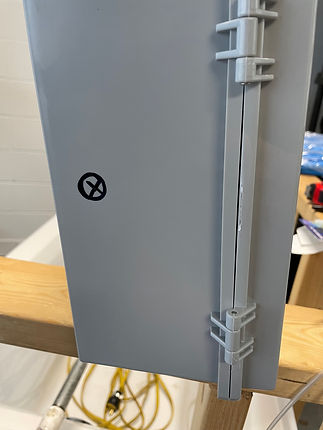
This is where the box will be mounted.
The pumps will be installed on the front end of the tub just below the niche shelf. The plastic tubing can easily be run from the product containers to the faucet in the shortest distance possible from there. The original plan was to run the tubing through the inside of the faucet and out near the spout. After inspecting the faucet, I can see there is not enough space for this. Instead we will run the tubes along the underside of the faucet and secure them with silicone adhesive.
The space inside the faucet is completely sealed so there is no room to run
the tubing.
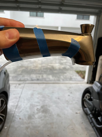
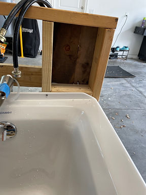
This is how the tubing will run. Its discreet enough that it won't affect the aesthetics of the tub much and will still allow the products to be dispensed directly near the flow of water. The tubes may even be painted at some point. In future improvements, a faucet that allows space on the interior to discreetly run tubing would be ideal.
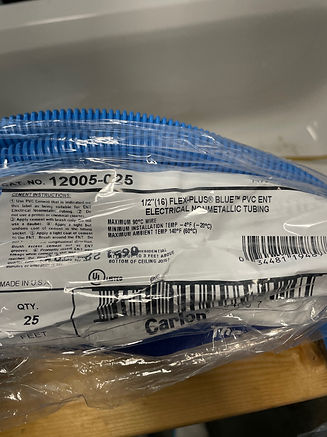
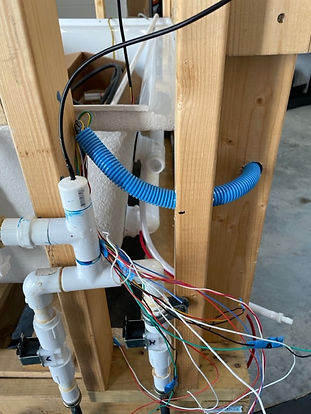
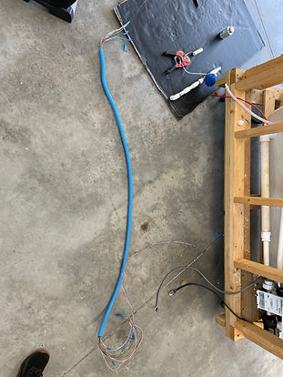
To further protect the electronics from water, I purchased some water proof electrical tubing to run all of the wires through. This will ensure they stay safe from moisture, as well as create a cleaner and more professional look.
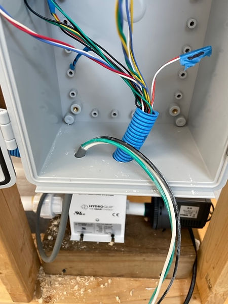
The IPV6 case also requires us to add an exit for the wires to pass through. I debated using a rubber grommet but ultimately decided that boring a hole directly in the side, running the electrical tub through, and then sealing back off with waterproof silicone would be the best course of action. I marked the side of the case where I plan to drill. I am waiting until I get a new drill bit so as not to crack the casing.
Ruben brought the flowmeter over which changes the layout of the plumbing. We learned that there are two types of threading, NPT and BSPT. Some adjustments will need to be made but shouldn't create any issue with the overall design. My next trip to the hardware store I will bring the pieces that need to be fitted and finish the plumbing. While I have the input valves apart, I also plan to realign the solenoids so the wiring poles are both facing inward. This will make it easier to access and wire as well as create a more streamlined look.
We also figured a better way to install the thermistors into the tub. By using PVC "T" connectors at the flowmeter and the drain, we can insert the into caps and seal them with silicone. This will place them out of the way of the direct water flow but still capable of measuring the water at the input and at the lowest part of the tub without the need to drill into the tub.
Ruben - Since the water pump/heater uses an air switch with a 15 minute timer to shut off, leaving it on and controlling the outlet would not work. Kenneth suggested we open it up to see if we can control it directly with the microcontroller. He also got the wiring diagram for the pump from the manufacturer. After disassembling the pump and comparing the physical wiring to the diagram, we can remove the air switch and wire in a relay to control the pump. The code will have to have a timer to reactivate the pump after the 15minute built in mechanical timer shuts it off it needed. Since the pump can draw over 10A, a high powered relay was needed.
I also built and tested the circuit to control the peristaltic pumps. The circuit design is similar to the solenoid design, and the test code cycles the pump on and off in one second intervals to verify functionality.
After building and testing the code/circuit for the temperature sensor, there was a .5 to 1 degree variance compared to the digital thermometer. Also since the temperature sensor is a thermistor, it took longer to adjust to rapid changes in temperature. The digital thermometer instantly adjusted when transitioning from room temperature to ice cold water, while the thermistor took close to a minute to reach the same reading as the digital thermometer. With this information, we are changing to using DS18B20 temperature sensors which should provide the more immediate reading needed.














Kenneth - At the suggestion of the review panel, I did some more research on similar products on the market. Specifically, Japanese style tubs. I found that while Japanese culture more normalizes the bath experience, they still lack the smart features our product provides. Most products were soaking tubs with heating elements to maintain temperature during soaking. Most tubs were also free standing. More akin to an indoor hot tub for recreational use. I made a comparison chart below and have provided a link to the respective websites below.
Aquatica True Ofuro Tranquility Heated Japanese Bathtub - $10,100
Hot Stoic 2.0 - $9,700
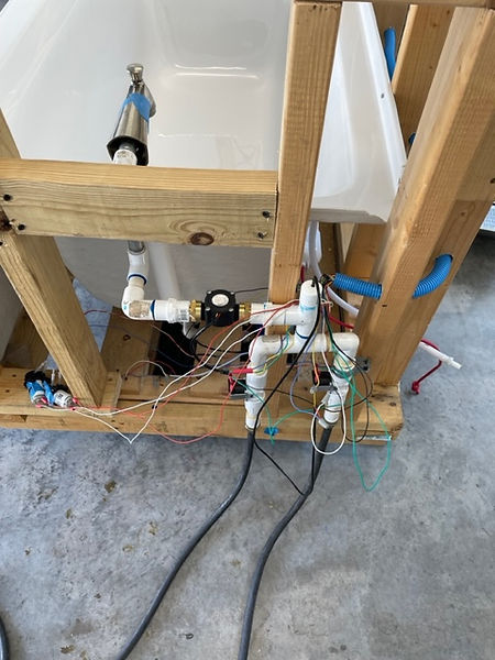
I was able to finish the dry fit plumbing this week as well as adding in the electrical tubing to run wires. The IPV6 waterproof box is mounted and a passthrough for the electrical tubing was made. Once wiring is complete, it will be sealed with waterproof silicone. The flowmeter has been added and the solenoids were moved for easier access during wiring. Updated pictures below.
Here is the electrical tubing run through the wall frame. The tubing enters the box from the bottom since that was the safest way to maintain waterproof capability.
The plumbing had to be redirected at a 90 degree angle since the flowmeter added so much length to the profile. This allowed me to secure the plumbing safely to the frame and compensate for the torque on the pipes.
The drain will also run off at a 90 degree angle so it is easier to show the ball valve during operation.
The niche shelf is built. This is where the essential oil and aromatherapy products will be stored.
With a little ingenuity I was able to drill holes in the faucet to hide most of the tubing for product dispensing. This creates a much cleaner, uniform look.
Ruben - This weeks goal was to finish getting the final three components working and to continue working on the app. First, changing the temperature sensor provided the exact desired results. The new sensor read similar values to the test digital thermometer used, and adjusted to rapidly changing temperatures quickly. The temperature readings in the image below are taken in 500ms intervals. The sensor was able to detect an 11 degree drop in temperature in 4 seconds.
For controlling the ball valve, the schematic below was used with some minor changes. Since only one relay is used, only one digital input from the Arduino is used. Also since we want the ball valve to be open unless specified, the open valve and close valve wires are switched so the open valve wire is normally closed.
The water heater is connected in a similar manner to the ball valve. The air pressure switch that normally controls it was removed, and a high power relay was wired in its place. With one connection to the normally open contact and one on the common ground the pump should have turned on when the relay closed. However the relay used has a connector that is set to a low signal activation when shipped. Once this was changed, the relay began working on a high signal activation. The pump was only ran for a second to test functionality since it can overheat without water flowing. To handle the current of the pump, 14 gauge wire was used, sourced from an old power cord.
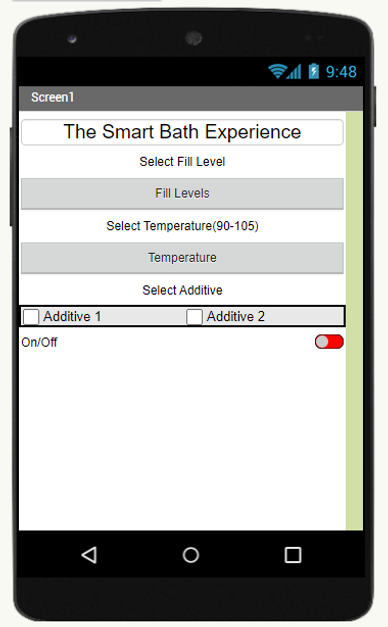
The first version of the app (left) had an issue where multiple fill levels could be selected. This is being revised to where only one will be able to be selected. Version 2 (right) fixes the issue of multiple selections from version 1, and it replaces the slider with a list of temperatures from 90-105 for the user to pick from to better tailor the experience to the users preferences.
Kenneth - I was able to get my hands on the ball valve for the drain this week. Of course, the plumbing that I had planned was incorrect. A trip to the hardware store and I was able to find and better alternative anyway. The drain valve has been fully installed onto the tub. I was able to fit the valve in the spot I originally anticipated for ease of access and viewing.
I also received the thermostats this week. I drilled a hole into the top of a pvc cap and ran the wires of the thermometers through. I used JB weld to attach them, then used tape to hold them at a 90 degree angle over night to cure in place. I was able to install them into the respective spots in the plumbing. One after the hot/cold inputs, and one just before the drain valve.
A dry fitting of the thermometers through the PVC caps
Thermometers installed at a 90 degree vertical angle to ensure no water becomes trapped.
Ruben - This week I have continued to work on the program and app integration. The wifi integration has been unsuccessful so far. To test the program while working on the wifi issues, I duplicated the program to edit and hardcode variable values in to test the functionality. So far it is working as intended, but all situations have not been tested.
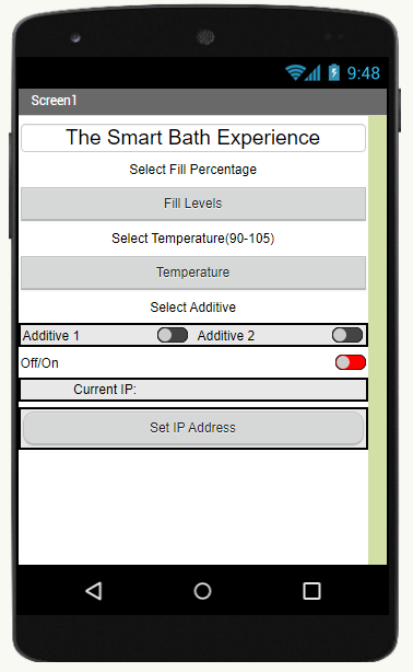
Version 3 of the app is shown below. Toggle switches have replaced check boxes for the additive control. Also a field to enter the IP address of the Arduino was added. This is necessary for the app to connect to the board.
The example program to initialize the board and connect it to my home WIFI network was successful. The image below shows the connection to my home network with the IP and MAC addresses redacted.
Follow up example programs to test the esp8266 WIFI board failed as the board stopped responding.
While discussing the project with my boss this week, he brought up an issue of liability. If a user begins the fill process while out of the house and something fails, such as a solenoid sticking open, serious water damage could be caused to the home. Also the full tub presents a drowning issue to small children or pets. If a babysitter or caregiver is unaware of the tub filled by someone on their way home, a dangerous situation is created that could lead to loss of life.
Between the WIFI issues, the liability issues, and no longer needing the WIFI Smart Plug, we have decided to transition to Bluetooth control. This will ensure that the user is inside of the house when the smart tub fills. All functionality will remain the same but the risks are reduced.
The HC-06 will be used instead of the ESP8266. For future development, if additional layers of safety are added, WIFI could be an option.
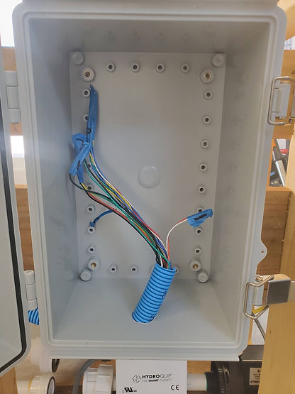
The mounting for the IP67 box is shown below. With the layout, a cleaner wiring path is created to connect the Arduino to the breadboard and the relays. All connections wires exiting the box into the cable tubing are oriented down to prevent water from damaging the electronics.
The air switch on the heat pump has been removed and a permanent 14 gauge wire cable is connected.
Group - With the tub assembly, code, and app completed, testing begins. Initial turn on found that the relays for both the ball valve and heat pump were set to high which closed the ball valve and turned on the heat pump. This was a carry over from individual component testing and was quickly fixed.
This did allow us to test switching the system off within the app, that successfully turned the heat pump off and opened the drain.
The second test revealed that the block of code containing the control of the hot and cold solenoids during the filling process was not transferred into the current version of the program.
It also revealed that although the temperature sensors were not reading properly, displaying 0 degrees. It is possible this is because while the data sheet says they can be powered by 3-6 volts, connecting to the 3.3V of the Arduino doesn't provide enough power to turn them on. When initially testing the sensors, they were connected to 5V. For test 3, they will be changed to 5V.
Ruben - Both the app and the Arduino code were completed this week. Initial Bluetooth communication was attempted using the BTSerial.read() instruction. This was returning data that would have to be converted if it was to be used. When trying to send the value 80, the instruction would return 56 48, which 56-48 = 8 and 48-48 = 0 giving the value of 80. However I found the instruction BTSerial.parseInt() which converts the serial data to an integer and directly gives the desired values.
For final assembly of the tub, I cut the appropriate wire length for all the components, and documented the wire colors as well as where they were going to be connected (power, ground, data). Kenneth and I ran the wires through the waterproof tubing and installed the tubing back into the frame of the tub.
I connected all the wires to the components and into the Arduino/breadboard, placing heat shrink where needed. The heat shrink will not be heated and the wires will not be managed until the system is functional incase changes need to be made.
Kenneth - This week I had to re enforce the seals on the temperature sensor. I added additional JB weld to the interior to prevent the waterflow from causing the sensors to shift during use.
The drain also had to be extended due to the placement of the temp sensors, ball valve, and frame of our tub.
An additional hole had to be drilled into the IP67 junction box for the wiring from the heat pump to the controlling relay, and the 12V power cable for the Arduino.
We ran all of the wiring through the corrugated tubing and into the ipv6 box. We we careful to label everything properly.
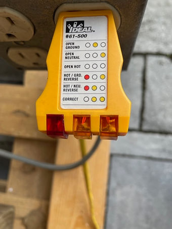
I tested the outlet box that I built and mounted to the frame of the tube and it I had the hot and neutral crossed. A quick revering of the connections and it was set for testing.
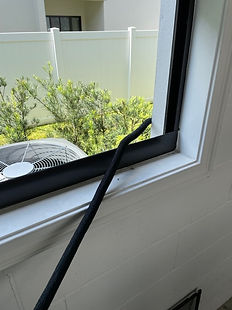
Once the wiring was complete, we moved to our first test phase. In order to run hot water to the tub, a hose was run from the upstairs laundry hot faucet, through the garage window, and the to the tub. The cold was connected to an outside faucet.
The next video documents our first attempt to run the system. It failed. The heat pump should not have turned on immediately. After some trouble shooting, the relay used to control the pump was reversed and the issue seemed to be solved. Testing will resume next week.
Group: Continued testing functionality. Two final issues remain before the system is fully functional. First the counter that is monitoring the fill level of the tub counts up to 73 liters then negates and starts counting back toward 0. Second, the peristaltic pumps are not turning on.
Ruben: The issue with the counters seems to be an overflow issue. The counter is stored as an Int type variable and is exceeding the number that can be stored in that variable type. I have changed it to a long variable for the next round of testing. This should provide us with a large enough space for the counter to increment for each fill amount.
The issue with the peristaltic pumps is due to my misunderstanding of the internal timer of the Arduino. The millis() function I thought was used to start the timer, which is not the case. The timer on the Arduino starts as soon as it powers on. Therefore to use it, the start time has to be designated as a variable taking a time stamp at the desired "start" time for the timer. Then to start the pumps 5 seconds after we close the drain, the condition must be millis() - our "start" time. This is updated and will be tested in our next session.
Every other function of the tub and app are functional. Once these final two issues are tested and resolved, the validation testing can begin.
Lastly the range of the bluetooth receiver was tested and has full connectivity anywhere inside the house, and remains connected all the way out to the street. Actual distance will be measured next testing session.
Kenneth: After some initial testing we realized the placement of out drain thermometer may not have enough circulated water to give an accurate reading of the tub temperature. To be sure, I moved the thermometer to the intake pipe on the heat pump. That way we can measure the water temp accurately.
Thermometer placed vertically at the heat pump intake.
I also created the bottles for the dispensable liquids to be stored. I am using mineral oil to simulate more viscous liquids such as essential and aroma therapy oils. We are using food coloring to differentiate between pump 1 and 2. Red for pump 1 and blue for pump 2. This should create a purple mixture while dispensing into the tub to show they are both working properly.











Week 23: 6/20/23 - 6/26/23
Group Testing - With everything in place, we began final testing and benchmarking this week. Video results with captions are all shown below. We believe we have ample proof to support our project works as intended and will begin finalizing our report and presentation in the coming weeks.
The first video shows the drain engaging as intended. As the water temperature from the faucet reaches the desired goal temp, the drain closes. Once the bath cycle has ended, the drain opens and water fully drains from the tub.
The next video we noticed the change from cold to hot water was unpleasant. We opted to adjust the code so both hot and cold run simultaneously once the water temperature reaches the threshold.
Our next run was a failure. The program was adjusted incorrectly not allowing the solenoids to switch properly. Adjustments were made and the program was fixed shortly after.
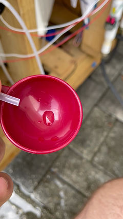
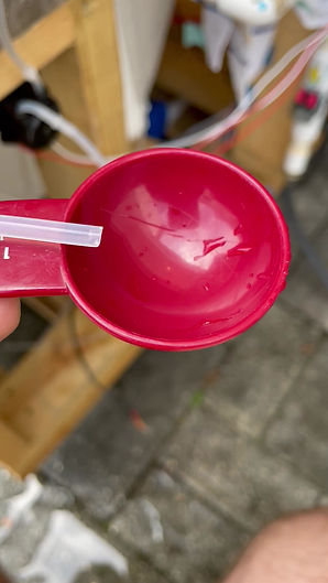
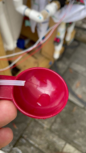
We tested the peristaltic pumps to see if our calculations of 22 second run time to dispense 1oz. was correct. Due to the product being mineral oil, the pump time needed to be adjusted. We measured the dispensed amount into a 1Tbsp measurement to show 0.5oz. The first video shows the pump running for 11seconds and then adjusted to 13 seconds to achieve a full 0.5oz amount.
Pump running for 11 seconds shows a slightly shorter amount that 0.5oz.
Below are dispensing amounts for pump 1 and pump 2 at 13 seconds. We ran these tests multiple times to ensure consistent accuracy. The final timer for the pumps during our testing cycle of the bath are doubled to 26 seconds to achieve one full once of product from each pump.
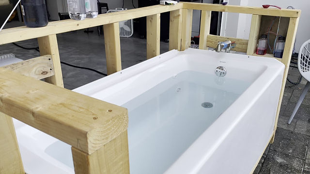
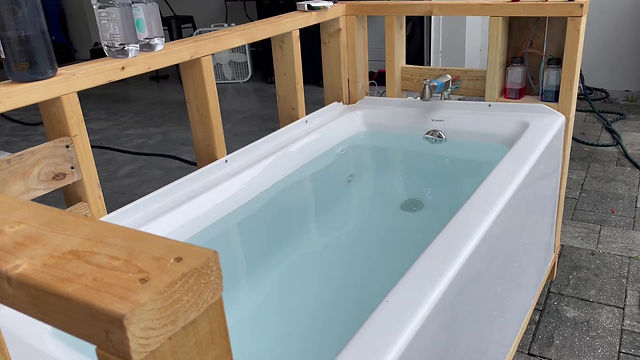
Our next video shows our first successful run without the heating pump. Water dispensed into the tub with the additives creating a purple color that can be seen in the beginning of the fill cycle. Temperature was checked throughout the cycle to ensure accuracy of the temperature sensors we installed. The ending result was a bath 101.3 degrees F while the input temperature was 102 degrees F. Well within the +/-3 degrees F criteria.
The next video shows the tub holding water after the fill cycle and the heating pump engaged. After waiting 7 minutes for the temperature to reach the upper threshold, we opted to reset the application at a lower temperature setting. This way we could record the pump turning on and off to prove our requirements.
In the next set of videos, we filled the tub and set the temperature to 97 degrees F. The first video confirms the tub filled, followed by a second video where we added cold water to speed up the process of dropping the temperature.
In this set of videos the water temper has dropped to -3 degrees Fahrenheit (94 degrees) of the target temperature (97 degrees). As expected, this turned the heating cycle on further proving our program and hardware were working as intended.
The final test was to ensure the heat cycle would turn off at +3 degrees (100 degrees) of the target temperature. The last video proves the program and hardware work as intended by turning the heat cycle off as the temperature reached 100.3 degrees F.
The results from our testing are displayed in the spreadsheet below. All criteria have been met. Due to the design of the heat pump, it is programmed to only turn on when the fill level is set to 80% or higher. For a safe operation, both the intake and output must be below the water level. With our tub, that only occurs when the water level is set to 80% or higher.
The feedback from our app review of 10 people is below. There were no complaints about the functionality or overall layout. However the aesthetic of the app was the biggest issue. Also some quality of life suggestions were made that would further enhance the user experience and allow them to customize the app for their uses.
The final version of the program is viewable as a PDF below. During testing we ran into an issue of the system randomly shutting off. After troubleshooting, it was found that the app was sending a '0' to the program. This appears to be the way the app pings the Bluetooth module to test the connection after being connected for a period of time. The issue was that when the program received a '0', the system will shut off. To fix this, the app and program were changed to use the value '30' to shut everything down.
When testing the range of the Bluetooth, we were able to maintain connection within the entirety of the house. Also, the connection maintained out the the mailbox and finally disconnected at 73 feet.







Week 24: 6/27/23 - 7/3/23
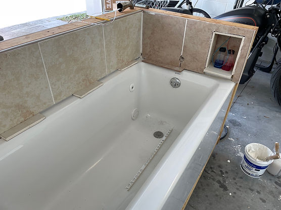
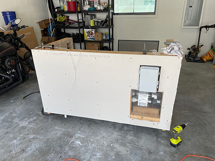
Kenneth - I added the finishing touches to the tub this week to make it final testing presentable. I added dry wall to to the farmed walls as well as tile that were scrapped from a previous project to the inside tub walls. I was also able to add a marble ledge for the niche shelf that houses the bath additives. I also cut out an access panel for the heat pump so it can be accessed from the adjacent wall. I used plexiglass to cover it so it can be viewed during testing. Pictures of the final results are below.





Week 25: 7/3/23 - 7/10/23
Week 26: 7/11/23 - 7/17/23
Group - We met this week to run some final testing to prove our engineering requirements. We were sure to capture screenshots of the program during the process with timestamps to display our results with more accuracy. Videos and screenshots of the final run are posted below.
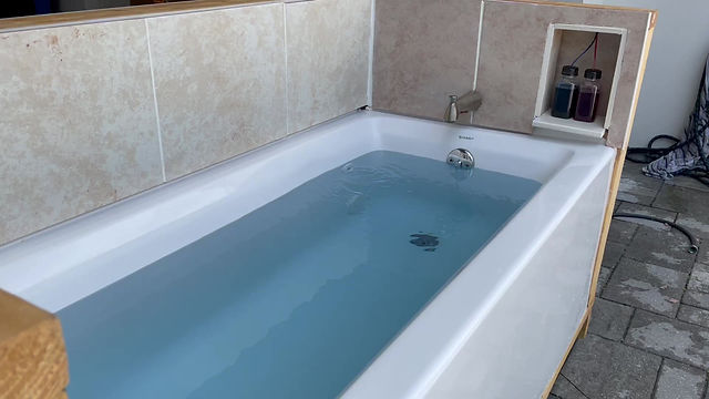
Group - We conducted testing this week with a person inside the tub during the fill process. The subject used was 6'1", 185lbs. The test was set at a 90% fill rate to ensure that this would not cause the tub to overflow at the maximum fill setting.
The water did not recede over the top of the tub but only a 0.5" space remained. This proves the maximum tub fill does work for our purposes, but a future build with a wider tub opening or an output jet that is installed lower on the tub wall would be ideal. An alternate tub would also mean the volume levels would need be recalculated.


Week 16: 5/1/23 - 5/7/23
Kenneth - Transported tub to final testing location. The tub framing and plumbing is mostly complete. The drain system will still need work. The solenoids for hot and cold water have been installed as well as the heating unit and pump. Some things that I noticed while building:
1. In future models where the shape of the tub can be controlled, flat surfaces should be used where the water intake and output meet the tub walls. This will help the contact surface remain leak free.
2. The pump we are using requires at least a 3" drop from pump to intake and at least a 3" rise from pump to output. This requires this tub to be completely full to demonstrate the heating element.
These issues seem to be limiting the build in some sense but could be avoided using a custom tub that just happens to be out of the budget for our prototype. Some pictures of the build progress are shown.
The solenoids are in place for the hot and cold water. They have been tested for water tightness. Quick release hose valves were added to the bottom for quick hook up during testing.
The flowmeter will be installed on this pipe. Whether it is installed vertically or horizontally will depend on the space in the area.
The water heater and pump installed. A block was used to support the pump to the proper height within the framing.
The intake valve and output for the water heater/pump. drilled through and sealed at the proper specifications.
Ruben - Discovered potential point of failure with drain solenoid overheating during the bath due to the time it is active. Initial plan to buy and torture test a second solenoid to determine how long before it failed was unsuccessful due to the solenoid out of stock. A ball valve was found to be a better solution since it only uses power when transitioning from one state to the other.
Group - Began waterproof testing. One small leak due to the hose fitting not being screwed on fully was found, but the plumbing tested watertight.


Week 17: 5/8/23 - 5/14/23
Kenneth - I began diving into the water heating pump now that it is plumbed into the framing. The pump is controlled by a SPDT air switch. This was not specified in the description before purchasing. Neither Ruben or myself have any experience with air switches but the wring diagram seems to show we can bypass the switch all together and hardwire the unit directly to the PCB with a relay. This is an ideal situation because it will allow us to omit the Wi-Fi plug from the equation. The pump is fitted with quick release valves so it can be removed and worked on. Ruben is taking it home to test it with the other hardware items.
A rough diagram of the air button in reference to the pump.
A couple images of the quick release on the pump after it was removed.
Ruben - I have began build the circuits and programming with the arduino to control them. I am initially writing basic programs to test the circuits and components before integrating them with one program that controls them all. Each test circuit will be rewired with neatly cut to length wires to prevent dethatching from the breadboard. Until the circuits are working properly, test jumpers are used as seen below. The solenoid test cycles it open and closed, and is verified working by an audible click of the solenoid.
Next was the flow rate sensor. To calculate the flow rate, from the data sheet, 2.25mL per pulse of the hall effect sensor is used to calculate the liters flowing through the sensor. Looking at the serial monitor of the Arduino, the calculated liters flowing through the sensor is shown.
With the change of the ball valve replacing the drain solenoid, a new circuit needed to be designed to control the operation. After some research, I was unable to find a schematic for circuit to control the valve with the components on hand. I attempted to create a circuit and consulted with Professor Young to see if it would work. After he modified it, he recommended that it would be less wiring and cleaner to use a relay. Since we are running 12V though our power adapter, I ordered a pair of 12V relays to control the valve.


Week 18: 5/15/23 - 5/21/23
Week 19: 5/22/23 - 5/29/23
Week 20: 5/29/23 - 6/5/23
Week 21: 6/6/23 - 6/12/23
Week 22: 6/13/23 - 6/19/23
Kenneth - Ruben and I were able to meet up for the first time since the framing of the tub was complete to start dry fitting the components onto the tub. First order was the ipv6 water proof case. Below is a picture of the mounting placement. It is just above the water pump so everything in that area can be accessed easily.
This is where the box will be mounted.
The pumps will be installed on the front end of the tub just below the niche shelf. The plastic tubing can easily be run from the product containers to the faucet in the shortest distance possible from there. The original plan was to run the tubing through the inside of the faucet and out near the spout. After inspecting the faucet, I can see there is not enough space for this. Instead we will run the tubes along the underside of the faucet and secure them with silicone adhesive.
The space inside the faucet is completely sealed so there is no room to run
the tubing.
This is how the tubing will run. Its discreet enough that it won't affect the aesthetics of the tub much and will still allow the products to be dispensed directly near the flow of water. The tubes may even be painted at some point. In future improvements, a faucet that allows space on the interior to discreetly run tubing would be ideal.
To further protect the electronics from water, I purchased some water proof electrical tubing to run all of the wires through. This will ensure they stay safe from moisture, as well as create a cleaner and more professional look.
The IPV6 case also requires us to add an exit for the wires to pass through. I debated using a rubber grommet but ultimately decided that boring a hole directly in the side, running the electrical tub through, and then sealing back off with waterproof silicone would be the best course of action. I marked the side of the case where I plan to drill. I am waiting until I get a new drill bit so as not to crack the casing.
Ruben brought the flowmeter over which changes the layout of the plumbing. We learned that there are two types of threading, NPT and BSPT. Some adjustments will need to be made but shouldn't create any issue with the overall design. My next trip to the hardware store I will bring the pieces that need to be fitted and finish the plumbing. While I have the input valves apart, I also plan to realign the solenoids so the wiring poles are both facing inward. This will make it easier to access and wire as well as create a more streamlined look.
We also figured a better way to install the thermistors into the tub. By using PVC "T" connectors at the flowmeter and the drain, we can insert the into caps and seal them with silicone. This will place them out of the way of the direct water flow but still capable of measuring the water at the input and at the lowest part of the tub without the need to drill into the tub.
Ruben - Since the water pump/heater uses an air switch with a 15 minute timer to shut off, leaving it on and controlling the outlet would not work. Kenneth suggested we open it up to see if we can control it directly with the microcontroller. He also got the wiring diagram for the pump from the manufacturer. After disassembling the pump and comparing the physical wiring to the diagram, we can remove the air switch and wire in a relay to control the pump. The code will have to have a timer to reactivate the pump after the 15minute built in mechanical timer shuts it off it needed. Since the pump can draw over 10A, a high powered relay was needed.
I also built and tested the circuit to control the peristaltic pumps. The circuit design is similar to the solenoid design, and the test code cycles the pump on and off in one second intervals to verify functionality.
After building and testing the code/circuit for the temperature sensor, there was a .5 to 1 degree variance compared to the digital thermometer. Also since the temperature sensor is a thermistor, it took longer to adjust to rapid changes in temperature. The digital thermometer instantly adjusted when transitioning from room temperature to ice cold water, while the thermistor took close to a minute to reach the same reading as the digital thermometer. With this information, we are changing to using DS18B20 temperature sensors which should provide the more immediate reading needed.


Kenneth - At the suggestion of the review panel, I did some more research on similar products on the market. Specifically, Japanese style tubs. I found that while Japanese culture more normalizes the bath experience, they still lack the smart features our product provides. Most products were soaking tubs with heating elements to maintain temperature during soaking. Most tubs were also free standing. More akin to an indoor hot tub for recreational use. I made a comparison chart below and have provided a link to the respective websites below.
Aquatica True Ofuro Tranquility Heated Japanese Bathtub - $10,100
Hot Stoic 2.0 - $9,700
I was able to finish the dry fit plumbing this week as well as adding in the electrical tubing to run wires. The IPV6 waterproof box is mounted and a passthrough for the electrical tubing was made. Once wiring is complete, it will be sealed with waterproof silicone. The flowmeter has been added and the solenoids were moved for easier access during wiring. Updated pictures below.
Here is the electrical tubing run through the wall frame. The tubing enters the box from the bottom since that was the safest way to maintain waterproof capability.
The plumbing had to be redirected at a 90 degree angle since the flowmeter added so much length to the profile. This allowed me to secure the plumbing safely to the frame and compensate for the torque on the pipes.
The drain will also run off at a 90 degree angle so it is easier to show the ball valve during operation.
The niche shelf is built. This is where the essential oil and aromatherapy products will be stored.
With a little ingenuity I was able to drill holes in the faucet to hide most of the tubing for product dispensing. This creates a much cleaner, uniform look.
Ruben - This weeks goal was to finish getting the final three components working and to continue working on the app. First, changing the temperature sensor provided the exact desired results. The new sensor read similar values to the test digital thermometer used, and adjusted to rapidly changing temperatures quickly. The temperature readings in the image below are taken in 500ms intervals. The sensor was able to detect an 11 degree drop in temperature in 4 seconds.
For controlling the ball valve, the schematic below was used with some minor changes. Since only one relay is used, only one digital input from the Arduino is used. Also since we want the ball valve to be open unless specified, the open valve and close valve wires are switched so the open valve wire is normally closed.
The water heater is connected in a similar manner to the ball valve. The air pressure switch that normally controls it was removed, and a high power relay was wired in its place. With one connection to the normally open contact and one on the common ground the pump should have turned on when the relay closed. However the relay used has a connector that is set to a low signal activation when shipped. Once this was changed, the relay began working on a high signal activation. The pump was only ran for a second to test functionality since it can overheat without water flowing. To handle the current of the pump, 14 gauge wire was used, sourced from an old power cord.
The first version of the app (left) had an issue where multiple fill levels could be selected. This is being revised to where only one will be able to be selected. Version 2 (right) fixes the issue of multiple selections from version 1, and it replaces the slider with a list of temperatures from 90-105 for the user to pick from to better tailor the experience to the users preferences.
Kenneth - I was able to get my hands on the ball valve for the drain this week. Of course, the plumbing that I had planned was incorrect. A trip to the hardware store and I was able to find and better alternative anyway. The drain valve has been fully installed onto the tub. I was able to fit the valve in the spot I originally anticipated for ease of access and viewing.
I also received the thermostats this week. I drilled a hole into the top of a pvc cap and ran the wires of the thermometers through. I used JB weld to attach them, then used tape to hold them at a 90 degree angle over night to cure in place. I was able to install them into the respective spots in the plumbing. One after the hot/cold inputs, and one just before the drain valve.
A dry fitting of the thermometers through the PVC caps
Thermometers installed at a 90 degree vertical angle to ensure no water becomes trapped.
Ruben - This week I have continued to work on the program and app integration. The wifi integration has been unsuccessful so far. To test the program while working on the wifi issues, I duplicated the program to edit and hardcode variable values in to test the functionality. So far it is working as intended, but all situations have not been tested.
Version 3 of the app is shown below. Toggle switches have replaced check boxes for the additive control. Also a field to enter the IP address of the Arduino was added. This is necessary for the app to connect to the board.
The example program to initialize the board and connect it to my home WIFI network was successful. The image below shows the connection to my home network with the IP and MAC addresses redacted.
Follow up example programs to test the esp8266 WIFI board failed as the board stopped responding.
While discussing the project with my boss this week, he brought up an issue of liability. If a user begins the fill process while out of the house and something fails, such as a solenoid sticking open, serious water damage could be caused to the home. Also the full tub presents a drowning issue to small children or pets. If a babysitter or caregiver is unaware of the tub filled by someone on their way home, a dangerous situation is created that could lead to loss of life.
Between the WIFI issues, the liability issues, and no longer needing the WIFI Smart Plug, we have decided to transition to Bluetooth control. This will ensure that the user is inside of the house when the smart tub fills. All functionality will remain the same but the risks are reduced.
The HC-06 will be used instead of the ESP8266. For future development, if additional layers of safety are added, WIFI could be an option.
The mounting for the IP67 box is shown below. With the layout, a cleaner wiring path is created to connect the Arduino to the breadboard and the relays. All connections wires exiting the box into the cable tubing are oriented down to prevent water from damaging the electronics.
The air switch on the heat pump has been removed and a permanent 14 gauge wire cable is connected.
Group - With the tub assembly, code, and app completed, testing begins. Initial turn on found that the relays for both the ball valve and heat pump were set to high which closed the ball valve and turned on the heat pump. This was a carry over from individual component testing and was quickly fixed.
This did allow us to test switching the system off within the app, that successfully turned the heat pump off and opened the drain.
The second test revealed that the block of code containing the control of the hot and cold solenoids during the filling process was not transferred into the current version of the program.
It also revealed that although the temperature sensors were not reading properly, displaying 0 degrees. It is possible this is because while the data sheet says they can be powered by 3-6 volts, connecting to the 3.3V of the Arduino doesn't provide enough power to turn them on. When initially testing the sensors, they were connected to 5V. For test 3, they will be changed to 5V.
Ruben - Both the app and the Arduino code were completed this week. Initial Bluetooth communication was attempted using the BTSerial.read() instruction. This was returning data that would have to be converted if it was to be used. When trying to send the value 80, the instruction would return 56 48, which 56-48 = 8 and 48-48 = 0 giving the value of 80. However I found the instruction BTSerial.parseInt() which converts the serial data to an integer and directly gives the desired values.
For final assembly of the tub, I cut the appropriate wire length for all the components, and documented the wire colors as well as where they were going to be connected (power, ground, data). Kenneth and I ran the wires through the waterproof tubing and installed the tubing back into the frame of the tub.
I connected all the wires to the components and into the Arduino/breadboard, placing heat shrink where needed. The heat shrink will not be heated and the wires will not be managed until the system is functional incase changes need to be made.
Kenneth - This week I had to re enforce the seals on the temperature sensor. I added additional JB weld to the interior to prevent the waterflow from causing the sensors to shift during use.
The drain also had to be extended due to the placement of the temp sensors, ball valve, and frame of our tub.
An additional hole had to be drilled into the IP67 junction box for the wiring from the heat pump to the controlling relay, and the 12V power cable for the Arduino.
We ran all of the wiring through the corrugated tubing and into the ipv6 box. We we careful to label everything properly.
I tested the outlet box that I built and mounted to the frame of the tube and it I had the hot and neutral crossed. A quick revering of the connections and it was set for testing.
Once the wiring was complete, we moved to our first test phase. In order to run hot water to the tub, a hose was run from the upstairs laundry hot faucet, through the garage window, and the to the tub. The cold was connected to an outside faucet.
The next video documents our first attempt to run the system. It failed. The heat pump should not have turned on immediately. After some trouble shooting, the relay used to control the pump was reversed and the issue seemed to be solved. Testing will resume next week.
Group: Continued testing functionality. Two final issues remain before the system is fully functional. First the counter that is monitoring the fill level of the tub counts up to 73 liters then negates and starts counting back toward 0. Second, the peristaltic pumps are not turning on.
Ruben: The issue with the counters seems to be an overflow issue. The counter is stored as an Int type variable and is exceeding the number that can be stored in that variable type. I have changed it to a long variable for the next round of testing. This should provide us with a large enough space for the counter to increment for each fill amount.
The issue with the peristaltic pumps is due to my misunderstanding of the internal timer of the Arduino. The millis() function I thought was used to start the timer, which is not the case. The timer on the Arduino starts as soon as it powers on. Therefore to use it, the start time has to be designated as a variable taking a time stamp at the desired "start" time for the timer. Then to start the pumps 5 seconds after we close the drain, the condition must be millis() - our "start" time. This is updated and will be tested in our next session.
Every other function of the tub and app are functional. Once these final two issues are tested and resolved, the validation testing can begin.
Lastly the range of the bluetooth receiver was tested and has full connectivity anywhere inside the house, and remains connected all the way out to the street. Actual distance will be measured next testing session.
Kenneth: After some initial testing we realized the placement of out drain thermometer may not have enough circulated water to give an accurate reading of the tub temperature. To be sure, I moved the thermometer to the intake pipe on the heat pump. That way we can measure the water temp accurately.
Thermometer placed vertically at the heat pump intake.
I also created the bottles for the dispensable liquids to be stored. I am using mineral oil to simulate more viscous liquids such as essential and aroma therapy oils. We are using food coloring to differentiate between pump 1 and 2. Red for pump 1 and blue for pump 2. This should create a purple mixture while dispensing into the tub to show they are both working properly.


Week 23: 6/20/23 - 6/26/23
Group Testing - With everything in place, we began final testing and benchmarking this week. Video results with captions are all shown below. We believe we have ample proof to support our project works as intended and will begin finalizing our report and presentation in the coming weeks.
The first video shows the drain engaging as intended. As the water temperature from the faucet reaches the desired goal temp, the drain closes. Once the bath cycle has ended, the drain opens and water fully drains from the tub.
The next video we noticed the change from cold to hot water was unpleasant. We opted to adjust the code so both hot and cold run simultaneously once the water temperature reaches the threshold.
Our next run was a failure. The program was adjusted incorrectly not allowing the solenoids to switch properly. Adjustments were made and the program was fixed shortly after.
We tested the peristaltic pumps to see if our calculations of 22 second run time to dispense 1oz. was correct. Due to the product being mineral oil, the pump time needed to be adjusted. We measured the dispensed amount into a 1Tbsp measurement to show 0.5oz. The first video shows the pump running for 11seconds and then adjusted to 13 seconds to achieve a full 0.5oz amount.
Pump running for 11 seconds shows a slightly shorter amount that 0.5oz.
Below are dispensing amounts for pump 1 and pump 2 at 13 seconds. We ran these tests multiple times to ensure consistent accuracy. The final timer for the pumps during our testing cycle of the bath are doubled to 26 seconds to achieve one full once of product from each pump.
Our next video shows our first successful run without the heating pump. Water dispensed into the tub with the additives creating a purple color that can be seen in the beginning of the fill cycle. Temperature was checked throughout the cycle to ensure accuracy of the temperature sensors we installed. The ending result was a bath 101.3 degrees F while the input temperature was 102 degrees F. Well within the +/-3 degrees F criteria.
The next video shows the tub holding water after the fill cycle and the heating pump engaged. After waiting 7 minutes for the temperature to reach the upper threshold, we opted to reset the application at a lower temperature setting. This way we could record the pump turning on and off to prove our requirements.
In the next set of videos, we filled the tub and set the temperature to 97 degrees F. The first video confirms the tub filled, followed by a second video where we added cold water to speed up the process of dropping the temperature.
In this set of videos the water temper has dropped to -3 degrees Fahrenheit (94 degrees) of the target temperature (97 degrees). As expected, this turned the heating cycle on further proving our program and hardware were working as intended.
The final test was to ensure the heat cycle would turn off at +3 degrees (100 degrees) of the target temperature. The last video proves the program and hardware work as intended by turning the heat cycle off as the temperature reached 100.3 degrees F.
The results from our testing are displayed in the spreadsheet below. All criteria have been met. Due to the design of the heat pump, it is programmed to only turn on when the fill level is set to 80% or higher. For a safe operation, both the intake and output must be below the water level. With our tub, that only occurs when the water level is set to 80% or higher.
The feedback from our app review of 10 people is below. There were no complaints about the functionality or overall layout. However the aesthetic of the app was the biggest issue. Also some quality of life suggestions were made that would further enhance the user experience and allow them to customize the app for their uses.
The final version of the program is viewable as a PDF below. During testing we ran into an issue of the system randomly shutting off. After troubleshooting, it was found that the app was sending a '0' to the program. This appears to be the way the app pings the Bluetooth module to test the connection after being connected for a period of time. The issue was that when the program received a '0', the system will shut off. To fix this, the app and program were changed to use the value '30' to shut everything down.
When testing the range of the Bluetooth, we were able to maintain connection within the entirety of the house. Also, the connection maintained out the the mailbox and finally disconnected at 73 feet.


Week 24: 6/27/23 - 7/10/23
Week 25: 7/11/23 - 7/17/23
Week 26: 7/17/23 - 7/24/23
Kenneth - I added the finishing touches to the tub this week to make it final testing presentable. I added dry wall to to the farmed walls as well as tile that were scrapped from a previous project to the inside tub walls. I was also able to add a marble ledge for the niche shelf that houses the bath additives. I also cut out an access panel for the heat pump so it can be accessed from the adjacent wall. I used plexiglass to cover it so it can be viewed during testing. Pictures of the final results are below.
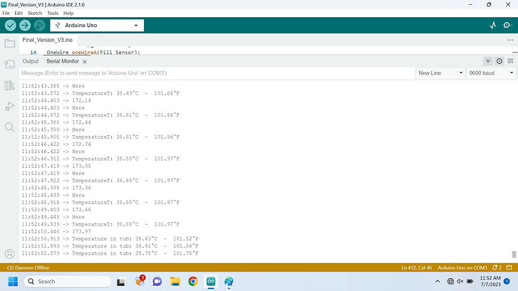
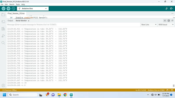
Group Testing - One final round of testing was conducted with the tub fully finished. The screenshots below show the Arduino serial monitor tracking the temperature and fill of the tub.
The previous images show the temperature in the tub during the filling process. When the fill amount reaches 173.66L, the solenoids close and the temp sensor in the tub begins monitoring the water.
Above the transition to the pump turning on is shown. Below shows the temperature being maintained.
With the final test completed, the requirements testing results table is updated.
Ruben - This week I completed the edits to chapter 1 of the report based on the feedback from the last meeting. I also completed report chapter 2, 3.1through 3.5, 4.2 through 4.5, and 5.1.





Ruben - Completed Table of contents, list of tables, list of figures, references, formatting, and adding a summary of testing results for report based on previous weeks meeting.
Group - Completed Project Presentation.
Senior Design EET 4950